Revisiting CVE-2023-21768
Introduction
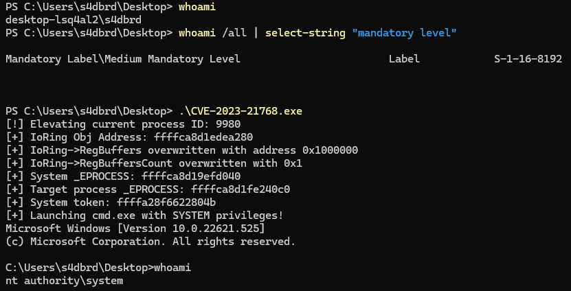
As kernel security continues to improve and modern exploit mitigations become more effective, attackers must rely on subtle primitives and creative post-exploitation techniques. CVE-2023-21768, a vulnerability in the AFD.sys driver, is one such example. It provides a limited write-what-where primitive that, when properly manipulated, enables full kernel memory read and write access and leads to privilege escalation.
This article takes a fresh look at CVE-2023-21768 from a low-level exploitation perspective, focusing on how the vulnerability can be weaponized using the Windows I/O Ring (IORING) interface to gain SYSTEM-level access. Through detailed analysis using tools like Binary Ninja and WinDbg, the post breaks down how specific fields inside the IORING object are corrupted to establish a fully controlled kernel memory interface.
Internals
The Ancillary Function Driver (AFD) is a critical kernel-mode component within Windows, acting as the foundational layer for Winsock API interactions. Essentially, AFD bridges user-mode applications with kernel-level networking operations, translating nearly every user-mode socket call, such as socket(), bind(), and connect(), into corresponding kernel-mode actions via AFD.sys.
AFD operates primarily through a dedicated device object (\Device\Afd) accessible by user-mode processes. Applications open this device to send I/O control requests (IOCTLs) for networking operations. Historically, this device was notably permissive, allowing interactions even from low-privileged or sandboxed processes until specific restrictions were implemented in Windows 8.1. Given its substantial complexity (implementing over 70 IOCTL handlers and totaling around 500KB of kernel code).
Socket Objects and Memory Management
Sockets in Windows are implemented as file objects managed internally by AFD. When an application creates a socket, it effectively calls NtCreateFile on the \Device\Afd device object, including specialized parameters within an extended attribute called the “AFD open packet.” AFD parses these parameters, allocating an internal structure (AFD_ENDPOINT) to represent the socket. This structure captures essential socket attributes, such as the protocol, addresses, and state (e.g., listening or connected).
AFD endpoints interface directly with underlying kernel transport stacks (typically TCP/IP) acting as a mediator between user-mode Winsock and lower-level kernel networking interfaces. Depending on the context and socket configuration, AFD can utilize either legacy Transport Driver Interface (TDI) or the newer Winsock Kernel (WSK) interfaces. This abstraction allows applications to maintain a consistent interface via Winsock APIs, regardless of the underlying network protocol specifics.
Transport Modes of AFD Endpoints
Modern Windows versions, define multiple transport modes for AFD endpoints based on how the socket is initially configured:
- TLI Mode (Transport Layer Interface): The default mode, employing modern kernel networking mechanisms, identifiable by the
TransportIsTLIflag within the endpoint structure. - Hybrid Mode: Activated when explicitly bound to well-known transport device objects (
\Device\Tcp,\Device\Udp, etc.), combining legacy TDI components with contemporary networking interfaces (indicated by theTdiTLHybridflag). - TDI Mode: A fully legacy mode used primarily for specialized or less common protocols (e.g., certain Bluetooth sockets), utilizing older kernel data structures (
TRANSPORT_ADDRESS) rather than contemporary formats (SOCKADDR).
Ancillary Structures and IOCTL Management
Internally, AFD maintains auxiliary structures necessary for robust socket operation, including:
- Queues and tables for tracking pending asynchronous requests.
- Structures dedicated to handling event polling and operations such as
selectorWSAPoll. - IRPs (I/O Request Packets) to perform asynchronous operations efficiently.
Many socket-related actions, like accepting connections, configuring socket options, or event notifications, are executed via specialized IOCTLs. Over decades, Microsoft’s development of AFD has led to a significant and stable set of these IOCTLs, prompting the introduction of a custom IOCTL encoding scheme due to the complexity and unique buffering requirements inherent to AFD operations.
Reversing
Patch Diffing
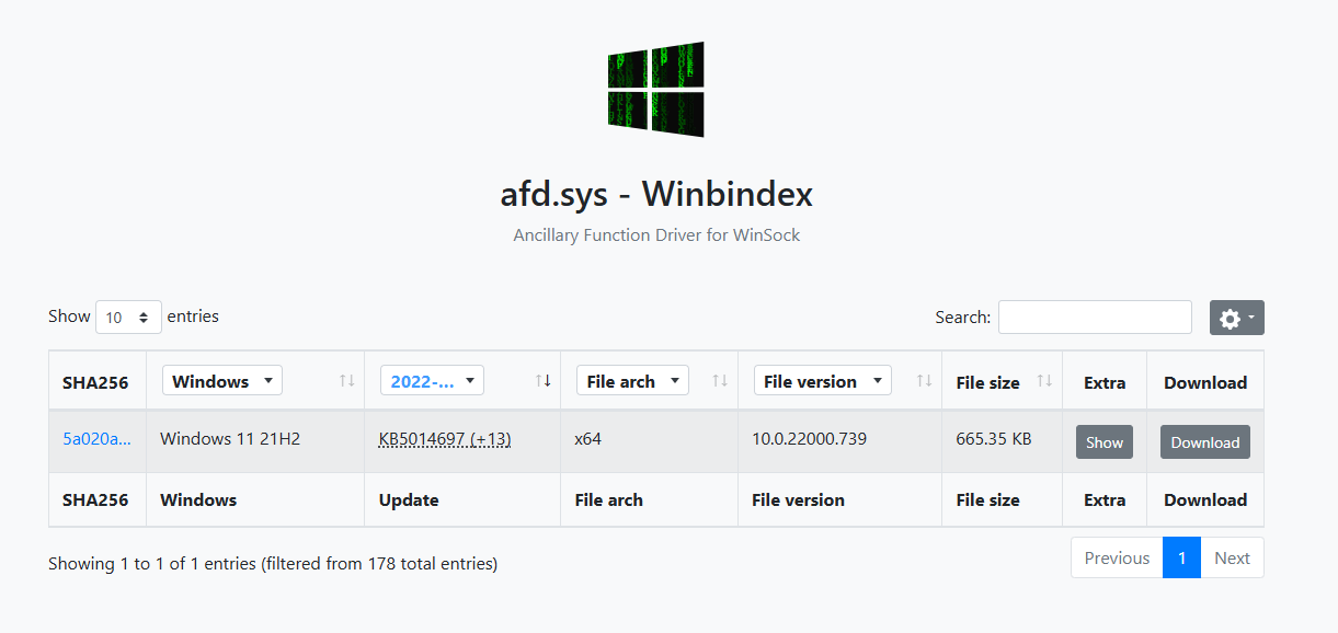
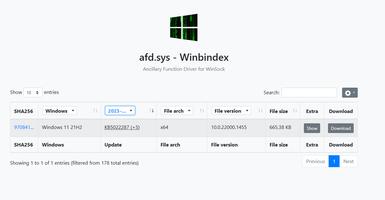
To analyze the changes introduced by the patch for CVE-2023-21768, we extracted and compared two versions of the afd.sys driver using Winbindex:
- Pre-patch: Version
10.0.22000.739, from update KB5014697 (Windows 11 21H2) - Post-patch: Version
10.0.22000.1455, from update KB5022287 (Windows 11 21H2)
Pre-patch:
Post-patch:
Binary Diffing
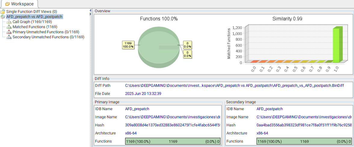
Using BinDiff through Binary Ninja, we confirmed that only a single function was modified:
AfdNotifyRemoveIoCompletion

Code Changes
Pre-patch version of AfdNotifyRemoveIoCompletion:
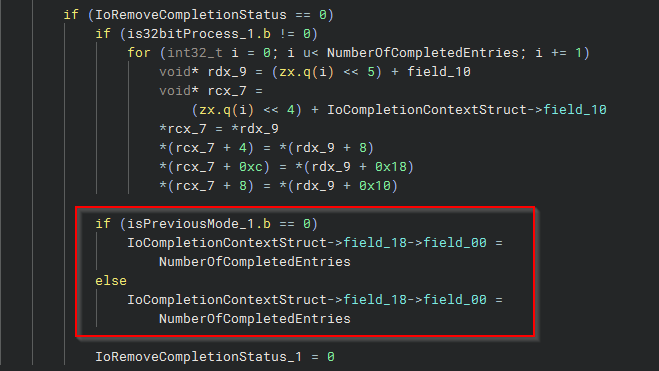
Code of post-patched function:
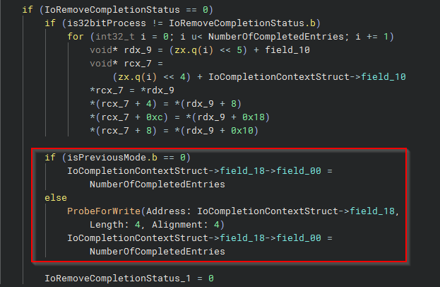
The patch introduces a crucial security check via ProbeForWrite, which validates that the memory region being written to is accessible in user mode. Its absence in the pre-patch version allowed user-mode processes to write to arbitrary kernel addresses, leading to a potential privilege escalation vulnerability.
Call Trace and Xref Analysis
The vulnerable function AfdNotifyRemoveIoCompletion is invoked by AfdNotifySock:

AfdNotifySock itself is referenced via data in the driver’s internal dispatch tables:

Investigating IOCTL Dispatch and Mapping
When examining the Windows AFD driver, IOCTL mapping is typically performed via the AfdIrpCallDispatch table. Function pointers in this table are indexed and matched to IOCTL values from AfdIoctlTable.
Dispatch Table Structure
Example:
0x1c004d660 // Base address of AfdIrpCallDispatch (index 0)
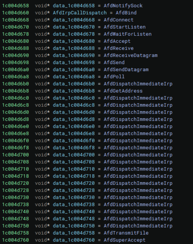
To find the IOCTL index of a specific handler, subtract the base address from the function pointer’s address and divide by 8 (64-bit pointer size).
Step 1: Calculating the Dispatch Table Index
Given:
AfdSuperAcceptaddress:0x1c004d760AfdIrpCallDispatchbase address:0x1c004d660We first compute the byte offset:Offset = 0x1c004d760 - 0x1c004d660 = 0x100Then divide by the pointer size (8 bytes):Index = 0x100 / 8 = 0x20 (32 decimal)
Step 2: Mapping to the IOCTL Table
The AfdIoctlTable is located at:
Base address = 0x1c004eef0
Since each IOCTL entry is 4 bytes, we compute the IOCTL offset:
Offset = 32 * 4 = 128 bytes (0x80)
So, the address of the IOCTL code is:
0x1c004eef0 + 0x80 = 0x1c004ef70
Inspecting the contents at this address yields:
IOCTL code: 0x12083
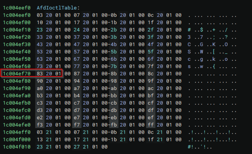
This confirms that AfdSuperAccept is invoked via IOCTL code 0x12083.
Special Case: AfdNotifySock and AfdImmediateCallDispatch
However, not all AFD functions are dispatched via AfdIrpCallDispatch. A notable exception is AfdNotifySock.
We observe that:
- The pointer to
AfdNotifySockis located at0x1c004d658, which precedes the start ofAfdIrpCallDispatch(0x1c004d660). - This indicates that
AfdNotifySockbelongs to a different dispatch mechanism: theAfdImmediateCallDispatchtable, which begins at0x1c004d410. This secondary dispatch table was first documented in Steven Vittitoe’s REcon presentation and later cited by IBM’s blog. It handles specific IOCTLs that require faster or immediate processing.
Calculating the IOCTL Index for AfdNotifySock
- Compute the offset from the start of
AfdImmediateCallDispatch:

Offset = 0x1c004d658 - 0x1c004d410 = 0x248
Index = 0x248 / 8 = 0x49 (73 decimal)
- Use this index to find the corresponding IOCTL in `AfdIoctlTable`:
IOCTL offset = 73 * 4 = 0x124
IOCTL address = 0x1c004eef0 + 0x124 = 0x1c004f014
- From the dump:
0x1c004f014 → 0x12127
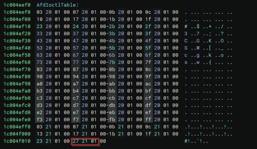
After identifying that the IOCTL code 0x12127 corresponds to index 73, where AfdNotifySock resides in the AfdImmediateCallDispatch table. I placed a kernel-mode breakpoint on AfdNotifySock to validate this link dynamically.
To trigger the IOCTL, I followed the method described in x86matthew’s blog, where a socket is created by calling NtCreateFile on \Device\Afd\Endpoint using extended attributes. After obtaining a valid socket handle, I issued a DeviceIoControl call with IOCTL 0x12127.

As expected, the breakpoint in AfdNotifySock was hit, confirming that this IOCTL code indeed invokes the AfdNotifySock handler in the AFD driver
Code
#include <windows.h>
#include <winternl.h>
#include <cstdio>

#pragma comment(lib, "ntdll.lib")

#define IOCTL_AFD_NOTIFY_SOCK 0x12127

typedef NTSTATUS(NTAPI* pNtCreateFile)(
    PHANDLE FileHandle,
    ACCESS_MASK DesiredAccess,
    POBJECT_ATTRIBUTES ObjectAttributes,
    PIO_STATUS_BLOCK IoStatusBlock,
    PLARGE_INTEGER AllocationSize,
    ULONG FileAttributes,
    ULONG ShareAccess,
    ULONG CreateDisposition,
    ULONG CreateOptions,
    PVOID EaBuffer,
    ULONG EaLength
    );

typedef NTSTATUS(NTAPI* pNtDeviceIoControlFile)(
    HANDLE FileHandle,
    HANDLE Event,
    PIO_APC_ROUTINE ApcRoutine,
    PVOID ApcContext,
    PIO_STATUS_BLOCK IoStatusBlock,
    ULONG IoControlCode,
    PVOID InputBuffer,
    ULONG InputBufferLength,
    PVOID OutputBuffer,
    ULONG OutputBufferLength
    );

int main() {
    HMODULE ntdll = GetModuleHandleW(L"ntdll.dll");
    auto NtCreateFile = (pNtCreateFile)GetProcAddress(ntdll, "NtCreateFile");
    auto NtDeviceIoControlFile = (pNtDeviceIoControlFile)GetProcAddress(ntdll, "NtDeviceIoControlFile");

    if (!NtCreateFile || !NtDeviceIoControlFile) {
        printf("[!] Failed to resolve ntdll functions\n");
        return 1;
    }

    HANDLE hSocket = nullptr;
    HANDLE hEvent = CreateEventW(nullptr, FALSE, FALSE, nullptr);
    if (!hEvent) {
        printf("[!] Failed to create event: %lu\n", GetLastError());
        return 1;
    }

    //
    // AFD extended attributes (as dictated by x86matthew's blog)
    //
    BYTE eaBuffer[] = {
        0x00, 0x00, 0x00, 0x00, 0x00, 0x0F, 0x1E, 0x00,
        0x41, 0x66, 0x64, 0x4F, 0x70, 0x65, 0x6E, 0x50,
        0x61, 0x63, 0x6B, 0x65, 0x74, 0x58, 0x58, 0x00,
        0x00, 0x00, 0x00, 0x00, 0x00, 0x00, 0x00, 0x00,
        0x02, 0x00, 0x00, 0x00, 0x01, 0x00, 0x00, 0x00,
        0x06, 0x00, 0x00, 0x00, 0x00, 0x00, 0x00, 0x00,
        0x00, 0x00, 0x00, 0x00, 0x60, 0xEF, 0x3D, 0x47, 0xFE
    };

    UNICODE_STRING afdName;
    RtlInitUnicodeString(&afdName, L"\\Device\\Afd\\Endpoint");

    OBJECT_ATTRIBUTES objAttr = { sizeof(OBJECT_ATTRIBUTES), nullptr, &afdName, OBJ_CASE_INSENSITIVE };
    IO_STATUS_BLOCK ioStatus = {};

    NTSTATUS status = NtCreateFile(
        &hSocket,
        0xC0140000, // GENERIC_READ | GENERIC_WRITE | SYNCHRONIZE
        &objAttr,
        &ioStatus,
        nullptr,
        0,
        FILE_SHARE_READ | FILE_SHARE_WRITE,
        FILE_OPEN,
        0,
        eaBuffer,
        sizeof(eaBuffer)
    );

    if (status != 0) {
        printf("[!] NtCreateFile failed: 0x%X\n", status);
        CloseHandle(hEvent);
        return 1;
    }

    printf("[+] AFD socket handle: 0x%p\n", hSocket);

    //
    // Call AfdNotifySock
    //
    status = NtDeviceIoControlFile(
        hSocket,
        hEvent,
        nullptr,
        nullptr,
        &ioStatus,
        IOCTL_AFD_NOTIFY_SOCK,
        nullptr,
        0,
        nullptr,
        0
    );

    if (status == STATUS_PENDING) {
        WaitForSingleObject(hEvent, INFINITE);
        status = ioStatus.Status;
    }

    if (!NT_SUCCESS(status)) {
        printf("[!] IOCTL 0x%X failed: 0x%X\n", IOCTL_AFD_NOTIFY_SOCK, status);
    }
    else {
        printf("[+] IOCTL 0x%X completed successfully.\n", IOCTL_AFD_NOTIFY_SOCK);
    }

    CloseHandle(hSocket);
    CloseHandle(hEvent);
    return 0;
}
Reverse Engineering Breakdown: AfdNotifySock

uint64_t AfdNotifySock(
    struct struct_1* EndpointContext,
    int64_t CompletionPort,
    char PreviousMode,
    void* InputBuffer,
    uint32_t InputBufferLength,
    void* OutputBuffer,
    uint32_t OutputBufferLength
)
This function appears to handle an IOCTL request passed through AfdImmediateCallDispatch. Based on its arguments, the function processes some form of input context (likely user-provided), interacts with I/O completion, and potentially returns status.
Initial Setup and Validation
1c006c9cf struct struct_1* AfdNotifyStruct = InputBuffer
- The input buffer from the IOCTL call is cast or interpreted as a
struct_1pointer. This struct likely represents user-supplied parameters or a context.
1c006c9d2 PreviousModeValue.b = PreviousMode
- Saves the caller’s previous processor mode (kernel or user) for conditional pointer validation later. In Windows,
PreviousModehelps determine if user-mode buffers need to be probed (i.e., validated withProbeForRead/Write).
1c006ca10 if (InputBufferLength != 0x30 || OutputBufferLength != 0)
The function validates that:
- The input buffer must be exactly
0x30bytes. - The output buffer must be empty (length 0). If either of these conditions fails, it returns an error:
1c006c9ff rbx = STATUS_INFO_LENGTH_MISMATCH
This is a standard NTSTATUS error for buffer size mismatches: 0xC0000004.
Reconstructed Input Structure: AfdNotifyStruct
The input structure passed to AfdNotifySock via the IOCTL call is expected to be exactly 0x30 bytes in size. This structure appears to control how I/O completion notifications are managed or delivered through AFD.
struct AfdNotifyStruct {
    HANDLE   CompletionPortHandle;   // Handle to a completion port object
    void*    NotificationBuffer;     // Pointer to an array of notification entries
    void*    CompletionRoutine;      // Callback function invoked upon notification
    void*    CompletionContext;      // Optional context parameter passed to the callback
    uint32_t NotificationCount;      // Number of notification entries
    uint32_t Timeout;                // Optional timeout in milliseconds
    uint32_t CompletionFlags;        // Flags that control behavior/validation of completion
};
The first field, CompletionPortHandle, is a handle to a system completion port and is passed to ObReferenceObjectByHandle to obtain a valid kernel object for further operations. The NotificationBuffer field points to an array of notification entries, each likely 24 bytes in size on 64-bit systems, and is processed in a loop based on the NotificationCount field, which must be non-zero.
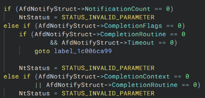
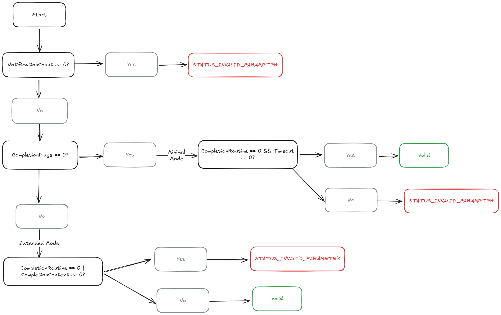
The CompletionRoutine field is a function pointer that, if specified, will be invoked for each notification. Its use is conditional: when CompletionFlags is non-zero, this field must be non-null. Similarly, the CompletionContext field provides optional user-defined data that is passed to the CompletionRoutine, and it too must be non-null when CompletionFlags is set. If CompletionFlags is zero, indicating a minimal or passive mode, then both CompletionRoutine and Timeout must be zero as well. If they are not, the structure is rejected.
The Timeout field defines an optional timeout in milliseconds and is only meaningful when a completion routine is provided. Finally, the CompletionFlags field acts as a control switch: when zero, the structure is validated as a minimal submission, and when non-zero, it triggers stricter validation and enables advanced completion behavior. Overall, this structure provides a flexible interface for managing batched I/O completions through AFD, with careful validation rules to guard against misuse depending on the chosen mode of operation.
The diagram below illustrates the internal validation logic used by AfdNotifySock when processing the AfdNotifyStruct structure. It shows how the structure transitions through minimal and extended modes based on the CompletionFlags field, and how the presence or absence of related fields like CompletionRoutine, CompletionContext, and Timeout determines whether the input is accepted or rejected.
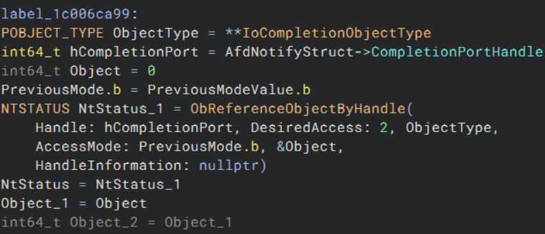
Once the structure is validated, the function proceeds to resolve the CompletionPortHandle by calling ObReferenceObjectByHandle. This system call safely converts the user-provided handle into a kernel object pointer, ensuring the caller has appropriate access rights (in this case, SYNCHRONIZE). The PreviousMode value is used to determine whether the caller originated from user-mode, and therefore whether access probing is needed.
From Binary Ninja, we can see that the object type passed to ObReferenceObjectByHandle is explicitly IoCompletionObjectType, meaning the handle must refer to an I/O Completion Object. This isn’t something one can infer purely from the function prototype. Thankfully, external resources like IBM’s blog and undocumented.ntinternals.net clarify that these objects are created in user mode using the NtCreateIoCompletion system call. Without a valid I/O completion object here, the call would fail.
The following snippet shows this reference in the disassembly:
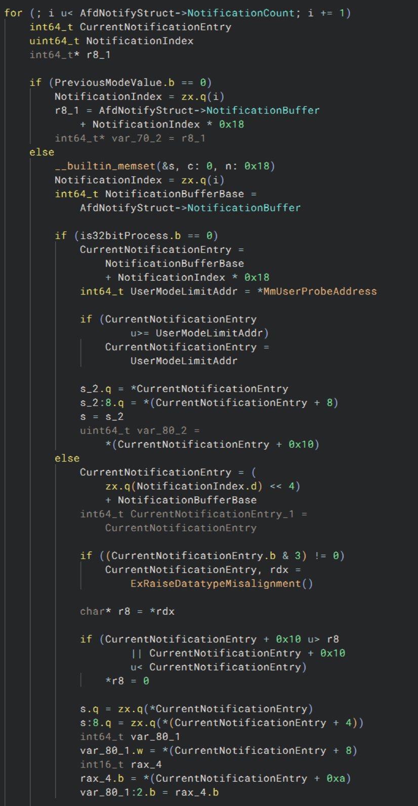
After the structure is validated and the I/O completion port handle is resolved, AfdNotifySock enters a for loop to process each notification entry. The loop runs up to NotificationCount, and for each iteration it calculates the address of the current entry by using the formula:
CurrentNotificationEntry = NotificationBuffer + i * 0x18;
Here, 0x18 is the size of each notification entry in 64-bit mode. If the caller originated from user mode (i.e., PreviousMode != 0), the code performs rigorous validation on each entry to ensure memory safety. It first compares the calculated pointer against *MmUserProbeAddress, which is the maximum address accessible in user mode. If the pointer exceeds that limit, it’s clamped to the boundary value. This ensures that the kernel doesn’t dereference invalid or potentially malicious user-mode addresses.
This pattern is common in kernel-mode code when accessing user-provided buffers, as it protects the system from elevation-of-privilege or memory corruption bugs. If the pointer passes this boundary check, the function reads the entry’s fields from memory. In some paths, it also verifies alignment (using & 3 != 0) and checks that the entire 24-byte structure does not wrap around the user-mode address space.
The snippet below demonstrates this logic in disassembly:
Once each notification entry has been processed and validated, the function transitions into its final steps. For each iteration of the loop, it invokes AfdNotifyProcessRegistration, which likely registers the individual notification with the completion port. However, a key detail here is that the EndpointContext pointer is only passed for the first notification (i == 0); for all subsequent entries, it is set to nullptr. This design indicates that the endpoint context is relevant only once per call, possibly to associate a single socket with multiple pending notifications.
if (i != 0)
    EndpointContext_1 = nullptr;
Following the registration, the status result is written back to the corresponding notification entry. If the caller is running in kernel mode (PreviousMode == 0), this write happens directly into the buffer:
*(AfdNotifyStruct->NotificationBuffer + NotificationIndex * 0x18 + 0x14) = ProcessRegistrationStatus;
For user-mode callers, the process is more cautious. The pointer to the status field is computed differently depending on whether the process is 32-bit or 64-bit. In 64-bit processes, it mirrors the kernel layout, while 32-bit mode adjusts the layout to match a packed structure:
if (is32bitProcess == 0)
    StatusFieldPtr = NotificationBuffer + NotificationIndex * 0x18 + 0x14;
else
    StatusFieldPtr = NotificationBuffer + 0x0C + (NotificationIndex << 4);
Before writing, the pointer is validated against MmUserProbeAddress to ensure the kernel doesn’t accidentally corrupt memory outside of the caller’s accessible space:
if (StatusFieldPtr >= *MmUserProbeAddress)
    StatusFieldPtr = *MmUserProbeAddress;
*StatusFieldPtr = ProcessRegistrationStatus;
Finally, once all notifications are processed and status codes have been stored, the function calls the handler we’ve been tracing toward: AfdNotifyRemoveIoCompletion.
NtStatus = AfdNotifyRemoveIoCompletion(
    PreviousMode,      // Access mode
    CompletionPort,    // I/O Completion Object
    AfdNotifyStruct    // Notification context
);
Buffer Preparation and Overflow Checking
The first step is to extract the CompletionFlags value, which determines how many I/O completion packets are expected. If this value is zero, the function returns immediately. Otherwise, it multiplies CompletionFlags * 0x20 (32 bytes per entry) to compute the total buffer size for 64-bit processes. This multiplication is checked for overflow using the high-part of the result (rdx); if non-zero, the operation fails early with STATUS_INTEGER_OVERFLOW.
If the caller is a 32-bit process, the size computation changes: CompletionFlags * 0x10 (16 bytes per entry) is used instead, again checking for overflow. These two paths ensure correct allocation regardless of architecture.
Handling User-Mode Buffers
If the caller is from user-mode (isPreviousMode != 0), the function probes the CompletionRoutine buffer for write access using ProbeForWrite, with appropriate size and alignment based on the process type (4-byte aligned for 32-bit, 8-byte for 64-bit). If the completion buffer is too large to fit on the stack, ExAllocatePool2 is used to dynamically allocate space.
Additionally, if a timeout is specified (TimeoutInMs != 0xFFFFFFFF), it is converted to negative 100-nanosecond units, as expected by the kernel, by multiplying by -0x2710. Otherwise, nullptr is passed to indicate no timeout.
Executing Completion Removal
At this point, the function invokes IoRemoveIoCompletion, passing in the calculated buffer address, completion context, and timeout.
IoRemoveCompletionStatus = IoRemoveIoCompletion(
    CompletionPort,
    CompletionRoutineBuffer,
    P,
    CompletionFlags,
    &NumberOfCompletedEntries,
    PreviousMode,
    TimeoutPtr,
    ...);
Post-Processing and Result Copying
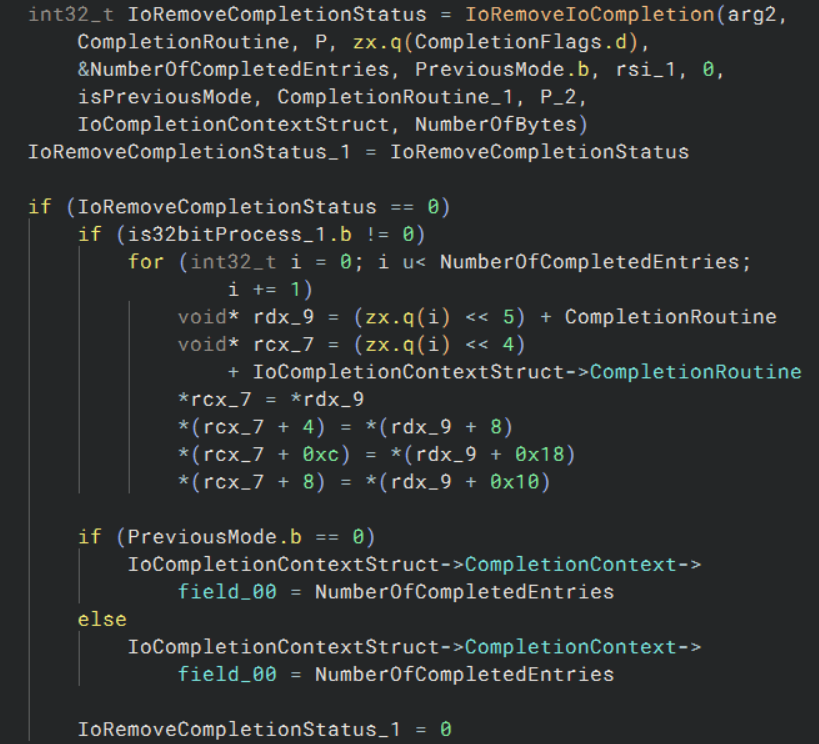
If the call to IoRemoveIoCompletion is successful and the process is 32-bit, the function repacks the results from the internal 64-bit aligned format into the smaller 32-bit user structure manually. This involves iterating through each entry and copying fields accordingly.
for (int32_t i = 0; i < NumberOfCompletedEntries; i++) {
    CopyEntry(i);
}
At the end of AfdNotifyRemoveIoCompletion, after removing the I/O completion entries, the function attempts to write back the number of entries to the output structure pointed to by CompletionContext.
if (PreviousMode.b == 0)
    IoCompletionContextStruct->CompletionContext->field_00 = NumberOfCompletedEntries;
else
    IoCompletionContextStruct->CompletionContext->field_00 = NumberOfCompletedEntries;
While this final write appears symmetrical in both branches, it only occurs if the preceding call to IoRemoveIoCompletion returns STATUS_SUCCESS. This return status is essential: if it fails, for instance, because the completion port queue is empty, the rest of the function (including this write) is never reached.
This is where a subtle but important behavior of IoRemoveIoCompletion comes into play. The function will only return success if at least one completion packet is already queued on the IoCompletionObject. Simply setting a timeout of 0 is not sufficient. If the queue is empty, the function fails early, regardless of how short the timeout is.
To ensure that the function proceeds successfully, we must manually enqueue a completion packet into the IoCompletionObject. This can be done using the undocumented function NtSetIoCompletion, which allows direct insertion of a packet into the port’s queue. Details on this function can be found in Undocumented NT Internals.
This aligns with the behavior of I/O Completion Ports described in the Windows Internals article, which emphasizes that completion ports are only active when there are packets to consume. Injecting one manually guarantees that IoRemoveIoCompletion returns successfully and that the rest of the completion handling code, including writing to the user-supplied structure, executes as intended.
This insight was also highlighted in IBM’s blog, where they correctly observed that without this step, the call chain silently fails before any interesting behavior is reached.
To support this behavior with actual implementation insight, we can refer to both Microsoft’s Windows Internals and a direct analysis of the kernel.
The Understanding the Windows I/O System article describes the internal flow of I/O Completion handling:
“When a server thread invokes
GetQueuedCompletionStatus, the system serviceNtRemoveIoCompletionis executed. After validating parameters and translating the completion port handle to a pointer to the port,NtRemoveIoCompletioncallsIoRemoveIoCompletion, which eventually callsKeRemoveQueueEx…”

To verify this in practice, I reverse-engineered IoRemoveIoCompletion from ntoskrnl.exe. As shown below, the call to KeRemoveQueueEx is responsible for fetching queued completion packets:
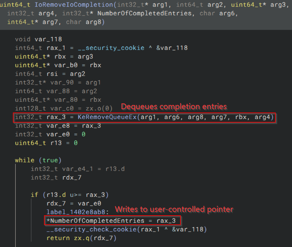
The return value from KeRemoveQueueEx directly determines whether IoRemoveIoCompletion proceeds to set NumberOfCompletedEntries. If nothing is dequeued, the function exits early.
This confirms, both from disassembly and supporting documentation, that IoRemoveIoCompletion will only proceed to write to the output structure if at least one completion entry is dequeued. If the completion queue is empty, the function exits early, bypassing any write.
While this behavior is not explicitly stated in IBM’s blog, it is observable in the reversing of the IoRemoveIoCompletion function itself, and is consistent with the design described in the Understanding the Windows I/O System article.
To validate the returned value, WinDbg was used to inspect the outcome of KeRemoveQueueEx:
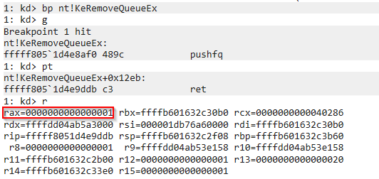
Here, rax holds the value 0x1, indicating that one completion entry was dequeued.
At this point in the exploit chain, the vulnerability gives reliable control over a write-what-where condition: specifically, a fixed value of 0x1 is written to an attacker-controlled address in kernel space. To turn this into a practical privilege escalation, the target address must correspond to a field that influences kernel control or memory behavior.
The structure chosen for this purpose is the I/O Ring, a relatively new kernel mechanism introduced in recent Windows versions. When initialized by a user process, it creates a pair of structures: one in user mode, and one in kernel mode (nt!_IORING_OBJECT). By writing 0x1 to a specific field within the kernel-mode IORING_OBJECT, it is possible to corrupt its internal state and gain arbitrary kernel read/write capabilities through legitimate syscalls.
Typically, the overwritten field is one that governs the behavior of the submission queue or enables user-accessible manipulation. Once corrupted, the ring interface can be abused to issue kernel read or write operations to arbitrary addresses, making token stealing or similar privilege escalations possible.
This exploitation strategy was previously documented by Yarden Shafir, who thoroughly reverse-engineered the I/O Ring internals and demonstrated how corruption of its fields can be weaponized. Her posts provide in-depth technical details:
These references are highly recommended for readers who want to understand the underlying mechanisms in depth. That said, to reinforce personal understanding, the next section will introduce the basics of I/O Rings and walk through why they are an ideal target in this exploit. Readers already familiar with this subsystem can skip ahead.
I/O Rings
Normally, performing an I/O operation in Windows requires a user-to-kernel transition. Each read, write, or file operation goes through the system call interface and involves expensive context switches. While this overhead is insignificant for occasional access, it becomes a major performance issue when dealing with large numbers of small operations, especially in high-performance or async I/O scenarios.
To solve this, Microsoft introduced I/O Rings, a mechanism that lets user-mode applications queue up I/O operations in memory-mapped ring buffers. These buffers are shared between user and kernel mode, allowing batching and asynchronous submission of many operations in a single call. The overall goal is to reduce the number of kernel transitions, improve performance, and make it easier to write scalable I/O heavy applications.
Key Components
At a high level, I/O Rings rely on the following concepts:
- Shared Ring Buffers: Circular buffers allocated in memory and mapped into both kernel and user address spaces. These are used to queue operations and read back results.
- NtCreateIoRing: A system call that initializes the ring and returns handles to the submission and completion queues.
- IORING_OBJECT: The kernel-side structure that manages the state of an I/O Ring. Its layout is shown below:
//0xd0 bytes (sizeof)
struct _IORING_OBJECT
{
    SHORT Type;                                                             //0x0
    SHORT Size;                                                             //0x2
    struct _NT_IORING_INFO UserInfo;                                        //0x8
    VOID* Section;                                                          //0x38
    struct _NT_IORING_SUBMISSION_QUEUE* SubmissionQueue;                    //0x40
    struct _MDL* CompletionQueueMdl;                                        //0x48
    struct _NT_IORING_COMPLETION_QUEUE* CompletionQueue;                    //0x50
    ULONGLONG ViewSize;                                                     //0x58
    LONG InSubmit;                                                          //0x60
    ULONGLONG CompletionLock;                                               //0x68
    ULONGLONG SubmitCount;                                                  //0x70
    ULONGLONG CompletionCount;                                              //0x78
    ULONGLONG CompletionWaitUntil;                                          //0x80
    struct _KEVENT CompletionEvent;                                         //0x88
    UCHAR SignalCompletionEvent;                                            //0xa0
    struct _KEVENT* CompletionUserEvent;                                    //0xa8
    ULONG RegBuffersCount;                                                  //0xb0
    struct _IOP_MC_BUFFER_ENTRY** RegBuffers;                               //0xb8
    ULONG RegFilesCount;                                                    //0xc0
    VOID** RegFiles;                                                        //0xc8
};
This structure contains everything from queue metadata and memory mappings to lock state and file/buffer registration.
- Submission Queue Entries (SQEs): Data structures that describe individual I/O operations (like read requests).
- NtSubmitIoRing: A system call used to submit queued SQEs to the kernel for processing.
Creating an I/O Ring
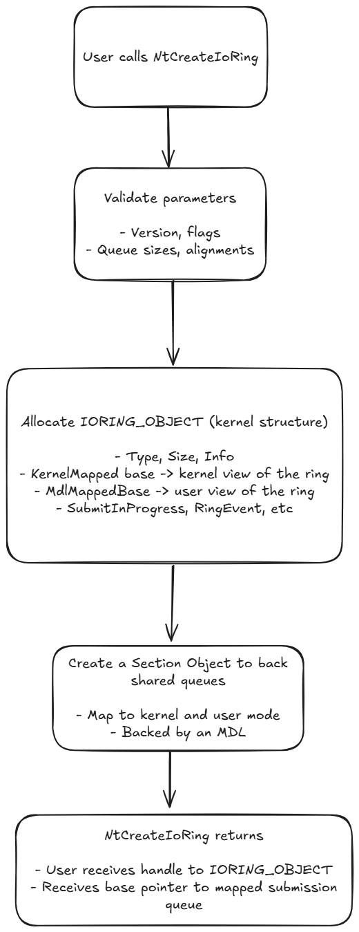
The process begins with the user calling NtCreateIoRing. This function creates an IORING_OBJECT in kernel memory and maps a pair of queues (submission and completion) into both kernel and user space using a shared memory section and a memory descriptor list (MDL). These queues are used for communication:
- Submission Queue: The user writes
NT_IORING_SQEentries here to request I/O. - Completion Queue: The kernel writes back results for each operation.
The following diagram illustrates the process described above, providing a visual summary of how an I/O Ring is initialized and mapped through NtCreateIoRing.
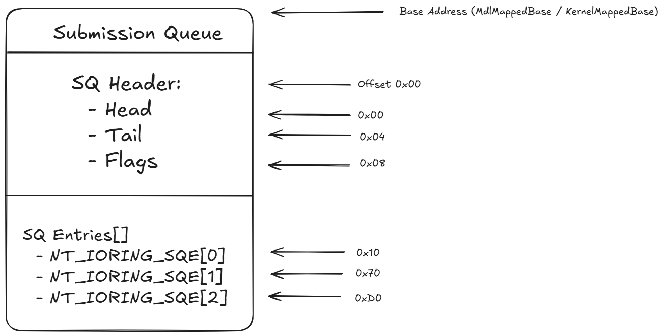
Once the I/O Ring is initialized, the user is given a base address pointing to the shared submission queue. At this point, operations can be written into the queue. The top of the submission queue contains a header with a few key fields:
Head: Index of the last processed entry.Tail: Index to stop processing at. This is updated by user mode to indicate how many new SQEs have been added.Flags: Operational flags.
Following the header is a contiguous array of NT_IORING_SQE structures. Each of these entries describes a specific I/O request:
- File handle to operate on
- Buffer address to read into
- File offset
- Number of bytes to read
- OpCode (like read operation)
The kernel processes all entries between Head and Tail. The difference between the two (Tail - Head) determines how many SQEs are ready for submission. When an operation is completed, its result is reported through the completion queue.
Operation Types and Flag Variants
There are four core operations that can be submitted using an I/O Ring, each specified by the OpCode field of the submission queue entry:
IORING_OP_READ: Reads data from a file into a buffer. TheFileReffield can either directly contain a file handle, or an index into a pre-registered file handle array (if theIORING_SQE_PREREGISTERED_FILEis set). TheBufferfield similarly may point directly to a buffer or reference an index into a pre-registered buffer array (if theIORING_SQE_PREREGISTERED_BUFFERis set).IORING_OP_WRITE: Writes data from a buffer to a file. TheFileReffield identifies the file to write to and can be either a raw file handle or an index into a pre-registered file handle array, depending on whether theIORING_SQE_PREREGISTERED_FILEflag is set. Similarly, theBufferReffield points to the source of the data, which may be a raw memory pointer or an index into a pre-registered buffer array, if theIORING_SQE_PREREGISTERED_BUFFERflag is set. Additional write-specific options (likeFILE_WRITE_FLAGS) are provided as part of the extendedNT_IORING_SQEunion when the operation is submitted.IORING_OP_FLUSH: Flushes any buffered data associated with a file to stable storage. TheFileReffield works the same way as in other operations, either as a raw file handle or an index into a pre-registered array. TheflushModeparameter controls flush behavior (e.g., whether metadata is also flushed), and is part of the SQE’s operation-specific union field. This operation does not use a buffer and does not transfer data, but it ensures durability of prior write operations.IORING_OP_REGISTER_FILES: Registers file handles in advance for later indexed use. TheBufferfield points to an array of file handles. These get duplicated into the kernel’sFileHandleArray.IORING_OP_REGISTER_BUFFERS: Registers output buffers in advance. TheBufferfield contains an array ofIORING_BUFFER_INFOentries, each containing an address and a length. These are copied intoBufferArrayint he kernel object.IORING_OP_CANCEL: Cancels a pending I/O operation. Works similarly toIORING_OP_READ, but theBufferfield points to theIO_STATUS_BLOCKthat should be canceled.
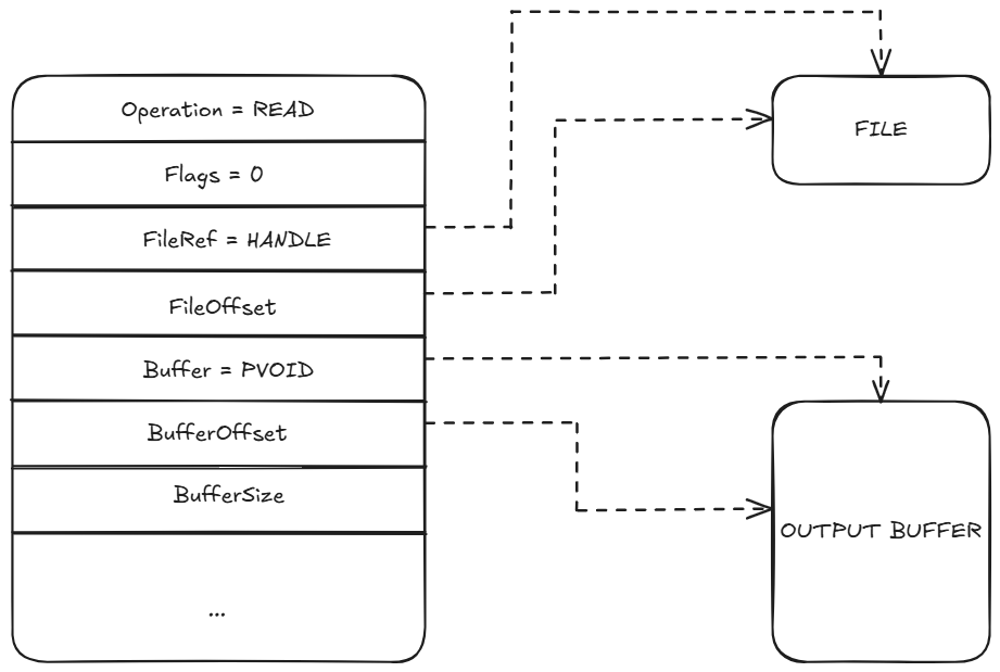
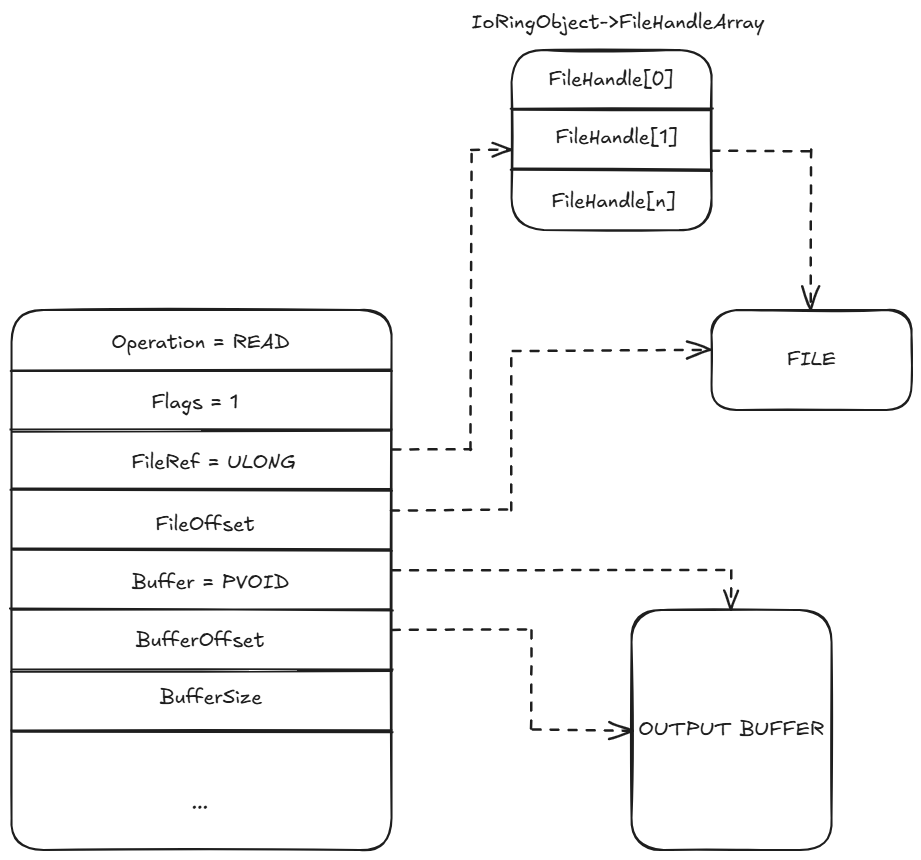
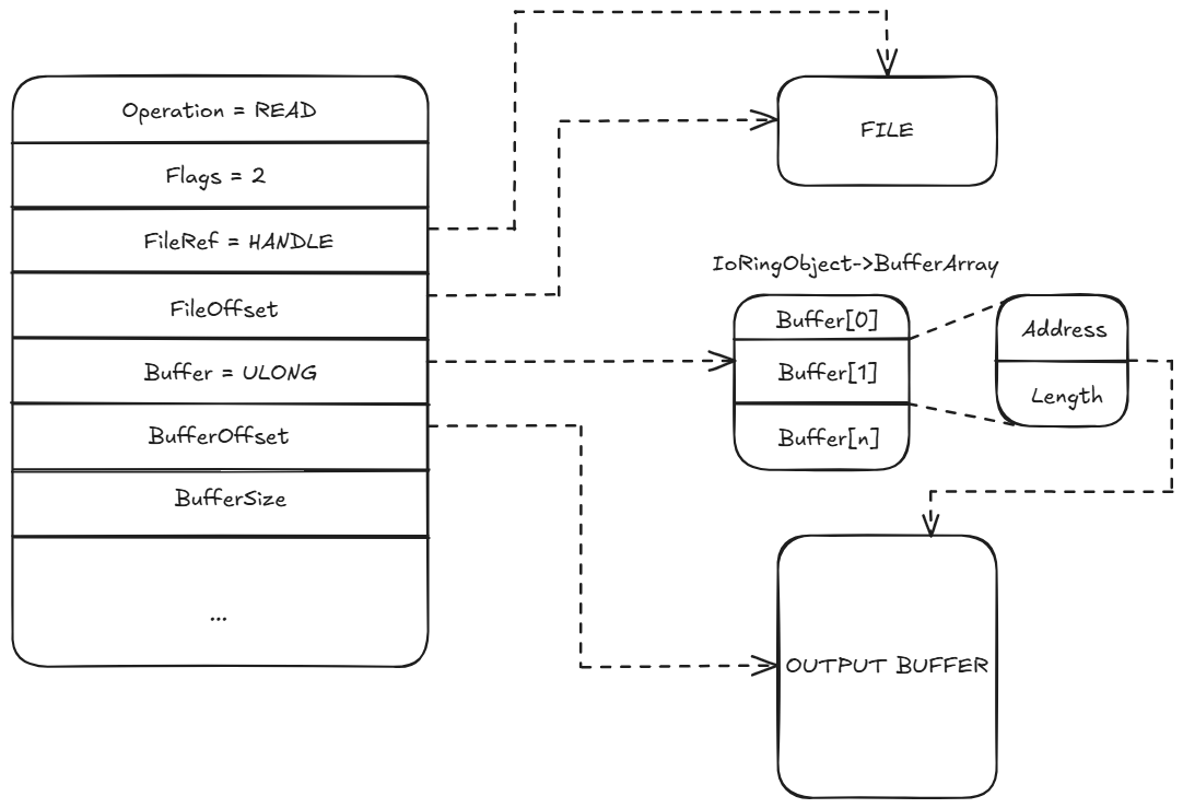
The behavior of the FileRef and Buffer fields in the submission queue entry depends on which flags are set. The following diagrams visualize how these flags modify interpretation of the fields:
Flags = 0
FileRef is used as a direct file handle and Buffer as a raw pointer to the output buffer.
Flags = 1 (IORING_SQE_PREREGISTERED_FILE)
FileRef is an index into a pre-registered file handle array. Buffer is a raw output buffer pointer.
Flag = 2 (IORING_SQE_PREREGISTERED_BUFFER)
FileRef is a direct file handle. Buffer is an index into a pre-registered buffer array
Flags = 3 (Both Preregistered)
FileRef and Buffer are both treated as indices into their respective kernel-managed arrays.
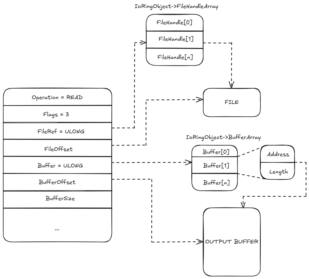
These combinations allow the I/O Ring to support different usage models, ranging from fully dynamic operations to fully pre-registered setups, which improve performance by avoiding repeated validation and mapping.
NT_IORING_SQE_FLAG_DRAIN_PRECEDING_OPS
When set, the entry will not execute until all previous operations have completed. This is useful for ordering dependencies.
New Implementations: Scatter / Gather
IORING_OP_READ_SCATTER
IORING_OP_READ_SCATTER is implemented through the kernel entry point IopIoRingDispatchReadScatter, which mirrors the design of IopIoRingDispatchWriteGather but performs the inverse operation. Upon receiving the submission entry, the kernel validates the operation code and flags, then uses IopIoRingReferenceFileObject to retrieve the target file object. It sets up the necessary parameters, including the array of pre-registered buffers that will receive the file data. Internally, the core logic is handled by IopReadFileScatter, which behaves similarly to the Windows API ReadFileScatter. The function expects an array of FILE_SEGMENT_ELEMENT structures representing disjoint memory regions, each of which must be sector-aligned and non-overlapping. The kernel checks the alignment and buffer size against the underlying device’s characteristics, such as sector granularity and transfer alignment, using fields from the device object (like AlignmentRequirement and SectorSize). If the buffers pass validation, an MDL is allocated via IoAllocateMdl, and the non-contiguous buffers are locked into physical memory with MmProbeAndLockSelectedPages. Once validated, an IRP is assembled with all scatter-gather parameters and dispatched using IopSynchronousServiceTail, allowing the device stack to process the request. Errors in alignment, memory range, or buffer registration are handled immediately and reflected in the resulting completion entry via IopCompleteIoRingEntry. This operation is especially useful for high-performance scenarios where incoming data must be distributed across multiple buffers without requiring additional copying or consolidation steps in user mode.
IORING_OP_WRITE_GATHER
Internally, IORING_OP_WRITE_GATHER is handled by the kernel via the IopIoRingDispatchWriteGather function, which begins by validating flags and resolving the file reference through IopIoRingReferenceFileObject. Once the file object is retrieved, it marks the SQE as processed and prepares the parameters for the actual write operation. The main logic is delegated to IopWriteFileGather, which is responsible for executing a scatter-gather write to the file. This function expects the buffers to be passed as an array of non-contiguous memory regions, each described by a FILE_SEGMENT_ELEMENT structure. It first verifies that the segment count and memory alignment conform to the device’s requirements, often based on sector size or alignment flags from the device object. If needed, the kernel allocates an MDL using IoAllocateMdl and locks the user buffers in memory with MmProbeAndLockSelectedPages. With all memory segments validated and pinned, it builds a properly configured IRP using IopAllocateIrpExReturn, fills out the necessary fields (such as the target file object, total length, buffer base, and completion information), and optionally references a completion event object passed from user mode. After constructing the IRP, it is sent to the I/O manager using IopSynchronousServiceTail, which hands off the request to the target device driver. If the operation fails at any stage, such as alignment mismatches, invalid segment counts, or memory errors, it returns an appropriate status code (e.g., STATUS_INVALID_PARAMETER, STATUS_DATATYPE_MISALIGNMENT), which is recorded in the completion queue entry. This mechanism enables high-throughput applications to efficiently write multiple buffers into a single file operation, while preserving the zero-copy and low-syscall design goals of the I/O Ring architecture.
Internally, IORING_OP_WRITE_GATHER is handled by the kernel via IopIoRingDispatchWriteGather, which resolves the target file object and marks the SQE as ready for execution. It invokes IopWriteFileGather, which receives an array of disjoint memory buffers via FILE_SEGMENT_ELEMENT structures. The kernel validates the alignment and size of each buffer against the device’s constraints, allocates an MDL with IoAllocateMdl, and locks the memory pages using MmProbeAndLockSelectedPages. After preparing the IRP with fields like file offset, total write size, and optional event handles, the request is dispatched through IopSynchronousServiceTail. If errors occur during validation or memory handling, the kernel signals completion with the appropriate status code in the CQE. The behavior closely resembles that of ReadFileScatter/WriteFileGather from user mode, but with improved performance and lower syscall overhead due to the batched and shared-buffer model of I/O Rings.
These operations leverage the same infrastructure and flag model as standard reads and writes but require arrays or structures to describe the scatter/gather regions.
Submitting and Processing I/O Ring Entries
Once all desired entries are written into the submission queue, the user-mode application can trigger processing by calling NtSubmitIoRing. This system call tells the kernel to begin processing the queued I/O requests based on their defined parameters.
Internally, NtSubmitIoRing walks through each pending submission queue entry, invoking IopProcessIoRingEntry. This function takes the IORING_OBJECT and the current NT_IORING_SQE and dispatches the corresponding I/O operation based on the entry’s OpCode. Once an operation is processed, the result is passed to IopIoRingDispatchComplete, which appends a completion result into the completion queue.
Like the submission queue, the completion queue starts with a header containing Head and Tail indices, followed by an array of entries. Each entry is of type IORING_CQE:
//0x18 bytes (sizeof)
struct _NT_IORING_CQE
{
    union
    {
        ULONGLONG UserData;                                                 //0x0
        ULONGLONG PaddingUserDataForWow;                                    //0x0
    };
    struct _IO_STATUS_BLOCK IoStatus;                                       //0x8
};
UserData: Copied from the corresponding submission entry.ResultCode: Contains the HRESULT or NTSTATUS result of the operation.Information: Typically the numbers of bytes read or written.
Completion Signaling
Originally, I/O Rings only supported a single signaling mechanism via the CompletionEvent field inside the IORING_OBJECT. This event was signaled only once all submitted I/O operations had completed. This model worked well for batch processing but wasn’t ideal for applications that needed to react to individual completions in real time.
// This event is set once all operations are complete
KEVENT CompletionEvent;
Then, Microsoft introduced per-entry notification through a new mechanism: CompletionUserEvent. This optional event gets signaled each time a new operation is completed and added to the completion queue. It enables fine-grained event-driven handling, where a dedicated thread can wait for individual completions as they arrive.
This change also introduced a new system call:
NtSetInformationIoRing(...)
Which allows the caller to register a user event. Internally, this sets the CompletionUserEvent pointer in the IORING_OBJECT. From that point forward, any new completed entry triggers a signal on this event, but only if it’s the first unprocessed entry in the queue, ensuring efficient notification without redundant signals.
// New field used for per-entry signaling
PKEVENT CompletionUserEvent;
To register the event from user mode, use:
SetIoRingCompletionEvent(HIORING ioRing, HANDLE hEvent);
This allows for a design where one thread performs I/O submission, while another continuously waits on the event and pops completions as they arrive.
Using I/O Rings from User Mode
Although NtCreateIoRing and related syscalls are undocumented and not intended for direct use, Microsoft provides official support through user-mode APIs exposed by KernelBase.dll. These APIs simplify the setup and usage of I/O Rings by wrapping the low-level functionality into higher-level functions. They manage the internal structures, format queue entries, and interact with the system on the developer’s behalf.
Creating the I/O Ring
The main entry point is CreateIoRing, which creates and initializes an I/O Ring instance:
HRESULT CreateIoRing(
  IORING_VERSION      ioringVersion,
  IORING_CREATE_FLAGS flags,
  UINT32              submissionQueueSize,
  UINT32              completionQueueSize,
  HIORING             *handle
);
The hIORING handle returned by this function points to an internal structure used by the system:
typedef struct _HIORING {
    ULONG SqePending;
    ULONG SqeCount;
    HANDLE handle;
    IORING_INFO Info;
    ULONG IoRingKernelAcceptedVersion;
} HIORING, *PHIORING;
This structure encapsulates internal metadata, including queue sizes, kernel version compatibility, and pending request counters. All other I/O Ring-related APIs will receive this handle as their first parameter.
Building Queue Entries
To issue I/O operations, user applications must construct Submission Queue Entries (SQEs). Since the internal SQE layout is not documented, Microsoft provides helper functions in KernelBase.dll to assist in building valid entries for each supported operation:
BuildIoRingReadFile
HRESULT BuildIoRingReadFile(
  HIORING           ioRing,
  IORING_HANDLE_REF fileRef,
  IORING_BUFFER_REF dataRef,
  UINT32            numberOfBytesToRead,
  UINT64            fileOffset,
  UINT_PTR          userData,
  IORING_SQE_FLAGS  sqeFlags
);
This function constructs a read operation entry. It supports either direct file handles and buffers (raw references), or indirect access via pre-registered arrays. The FileRef and DataRef structures both contain a Kind field indicating whether the reference is raw or an index.
`BuildIoRingWriteFile
STDAPI BuildIoRingWriteFile(
	_In_ HIORING ioRing,
    IORING_HANDLE_REF fileRef,
    IORING_BUFFER_REF bufferRef,
    UINT32 numberOfBytesToWrite,
    UINT64 fileOffset,
    FILE_WRITE_FLAGS writeFlags,
    UINT_PTR userData,
    IORING_SQE_FLAGS sqeFlags
);
BuildIoRingFlushFile
STDAPI BuildIoRingFlushFile (
    _In_ HIORING ioRing,
    IORING_HANDLE_REF fileRef,
    FILE_FLUSH_MODE flushMode,
    UINT_PTR userData,
    IORING_SQE_FLAGS sqeFlags
);
BuildIoRingRegisterFileHandles and BuildIoRingRegisterBuffers
These functions register arrays of file handles or buffers for reuse across multiple operations:
HRESULT BuildIoRingRegisterFileHandles(
  HIORING         ioRing,
  UINT32          count,
  HANDLE const [] handles,
  UINT_PTR        userData
);

HRESULT BuildIoRingRegisterBuffers(
  HIORING                     ioRing,
  UINT32                      count,
  IORING_BUFFER_INFO const [] buffers,
  UINT_PTR                    userData
);
Handlesis an array ofHANDLEs to register.Buffersis an array ofIORING_BUFFER_INFOstructures:
typedef struct _IORING_BUFFER_INFO {
    PVOID Address;
    ULONG Length;
} IORING_BUFFER_INFO, *PIORING_BUFFER_INFO;
BuildIoRingCancelRequest
HRESULT BuildIoRingCancelRequest(
  HIORING           ioRing,
  IORING_HANDLE_REF file,
  UINT_PTR          opToCancel,
  UINT_PTR          userData
);
This function constructs a cancellation request for a previously issued operation. It supports both raw and registered file handles.
Submitting and Managing I/O
Once all entries are written, they can be submitted for processing using SubmitIoRing:
HRESULT SubmitIoRing(
  HIORING ioRing,
  UINT32  waitOperations,
  UINT32  milliseconds,
  UINT32  *submittedEntries
);
WaitOperationsspecifies how many operations the system should wait to complete.Millisecondssets a timeout.SubmittedEntriesreturns how many entries were actually submitted.
The system processes each entry and queues results into the completion queue. Applications should check the results in the completion queue rather than relying solely on the return value of SubmitIoRing.
Querying and Cleaning Up
To retrieve basic information about the I/O Ring:
HRESULT GetIoRingInfo(
  HIORING     ioRing,
  IORING_INFO *info
);
This function fills in a structure containing metadata such as:
typedef struct _IORING_INFO {
    IORING_VERSION IoRingVersion;
    IORING_CREATE_FLAGS Flags;
    ULONG SubmissionQueueSize;
    ULONG CompletionQueueSize;
} IORING_INFO, *PIORING_INFO;
Finally, once the I/O Ring is no longer needed, it can be released:
CloseIoRing(HIORING IoRingHandle);
This closes the I/O Ring handle and cleans up associated resources.
Achieving LPE with I/O Rings
To convert a limited write-what-where primitive into a fully capable arbitrary kernel read/write, internal fields of the IORING_OBJECT are overwritten. By modifying the RegBuffersCount and RegBuffers fields, the I/O Ring infrastructure can be repurposed into a programmable memory access interface within the kernel’s trust boundary.
The first step involves setting RegBuffersCount to 1. This field typically reflects the number of buffers registered through IORING_OP_REGISTER_BUFFERS, and its value determines whether submission queue entries that use pre-registered buffers are considered valid. When this count is forcibly set to 1, the kernel assumes that one buffer has been successfully registered, even if the registration did not occur. This allows subsequent I/O Ring submissions with the IORING_SQE_PREREGISTERED_BUFFER flag to bypass internal checks.
As previously observed in Binary Ninja, the function afd!AfdNotifyRemoveIoCompletion receives a user-controlled structure as its third argument. Within this structure, specific offsets are interpreted by the AFD driver to define a target address and the value to be written. By placing a kernel address at offset +0x18 and the value 0x1 at offset +0x20, the function performs a write to that location.
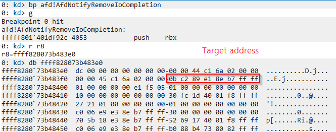
To modify the RegBuffersCount field of the IORING_OBJECT, the write targets offset +0xbb instead of +0xb0, which addresses only the least significant byte of the field. This ensures a precise update from 0x00 to 0x01 without affecting surrounding memory.
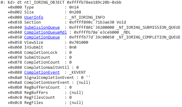
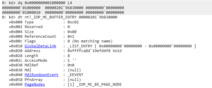
Following the first write, a second write is issued to populate the RegBuffers field. This pointer is set to a user-controlled virtual address, such as 0x10000000, where a forged IOP_MC_BUFFER_ENTRY will later be placed. With both fields corrupted, the kernel now believes a valid preregistered buffer exists and will use the fake metadata for I/O operations.
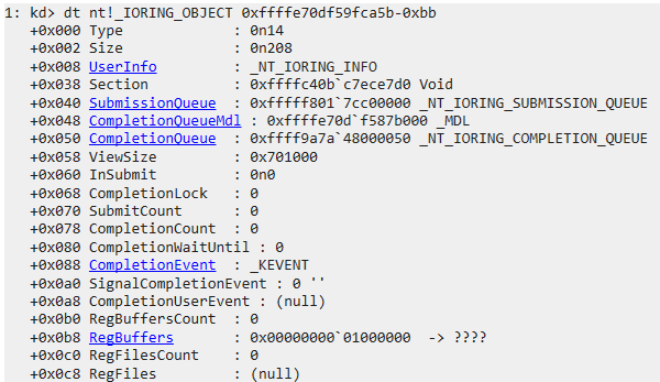
Once these conditions are met, a forged IOP_MC_BUFFER_ENTRY is written at the memory location pointed to by the RegBuffers field. This structure defines fields such as Address and Length, which are interpreted by the kernel when processing an I/O operation. The Address field is set to the target kernel memory address, and Length defines the number of bytes involved in the transfer.
How is Read Primitive achieved
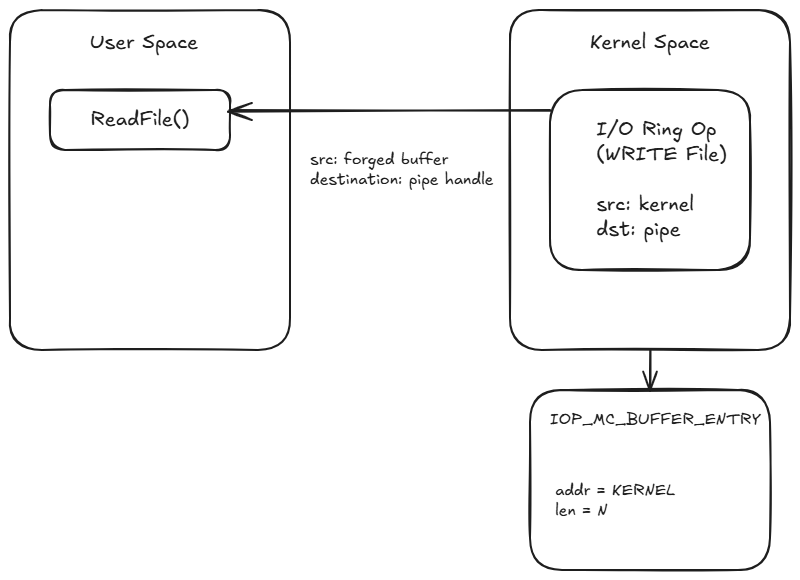
To implement an arbitrary kernel memory read, the I/O Ring interface is manipulated using a forged IOP_MC_BUFFER_ENTRY. This structure is placed in a user-controlled region pointed to by the RegBuffers field of the IORING_OBJECT. Its Address field is set to the target kernel address, and Length specifies how many bytes to read.
Although the goal is to read memory, the operation used is BuildIoRingWriteFile. This may seem counter-intuitive, but it functions as a read primitive because it causes the kernel to read from the buffer (pointing to kernel memory) and write the result into a file handle, which in this case is a pipe created by the exploit.
Once the operation is submitted, the kernel performs a write from the forged buffer (which actually points to kernel space) into the pipe. On the user side, calling ReadFile() on the pipe retrieves the data. This effectively leaks kernel memory contents into a user-mode buffer.
How is Write Primitive achieved
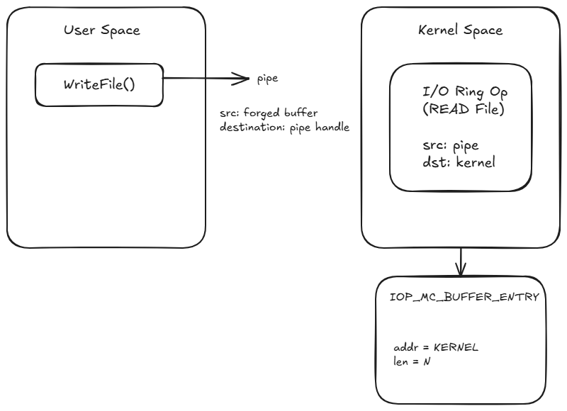
To perform an arbitrary write into kernel memory, the process begins by writing user-controlled data into a pipe using WriteFile(). A forged IOP_MC_BUFFER_ENTRY is crafted in user space, with its Address field pointing to the target kernel address and Length set to the number of bytes to write. This fake buffer is then placed into the RegBuffers array.
An I/O Ring operation is submitted using BuildIoRingReadFile(). Although it is a “read” operation, it causes the kernel to read from the pipe and write the data into the location specified by the forged buffer. Since the destination address resides in kernel space, this results in user-controlled data being written to arbitrary kernel memory.
Exploit Running
